2 – Getting to the Sole of the task.
The usual safety provisions apply. I won’t insult the capable but for those who are a little vague on what’s under discussion please read the safety stuff on the Information page.
First things first..
The first step is to strip the cast parts – the body and lever cap. The mouth plate can be left off for now, its sanding and filing comes later. Once the paint is gone – chemical removal (stripping – no not you!) is best although carefully blowtorching works okay – it may reveal some unsightly areas (again, not you!). The front edge, or toe, seen at top right was originally painted. I have removed some minimal pitting and it looks considerably better. The body will be repainted but only the rougher cast areas. Any contact surface or area previously milled will be flattened, blemishes removed and polished.
I have left the thumb dimples alone on the plane sides as they were fairly pleasing to look at and error free. If you needed to sort these out stripping and repainting before the final polishing is best. Top left (green ring) shows the sort of thing that comes to light after a preliminary rub over with 400 grit paper. During the sanding a light spraying with water is vital. This will keep the paper clean and ease the effort required. Make sure all work is done with the abrasive on a very flat surface. I use a 1/4″ (6mm) sheet of glass to flatten the sole of a plane but whatever is handy works. Something porous will need to be sealed first. MDF for example is quite flat and smooth but sucks water up like a sponge and will be neither flat nor smooth thereafter.
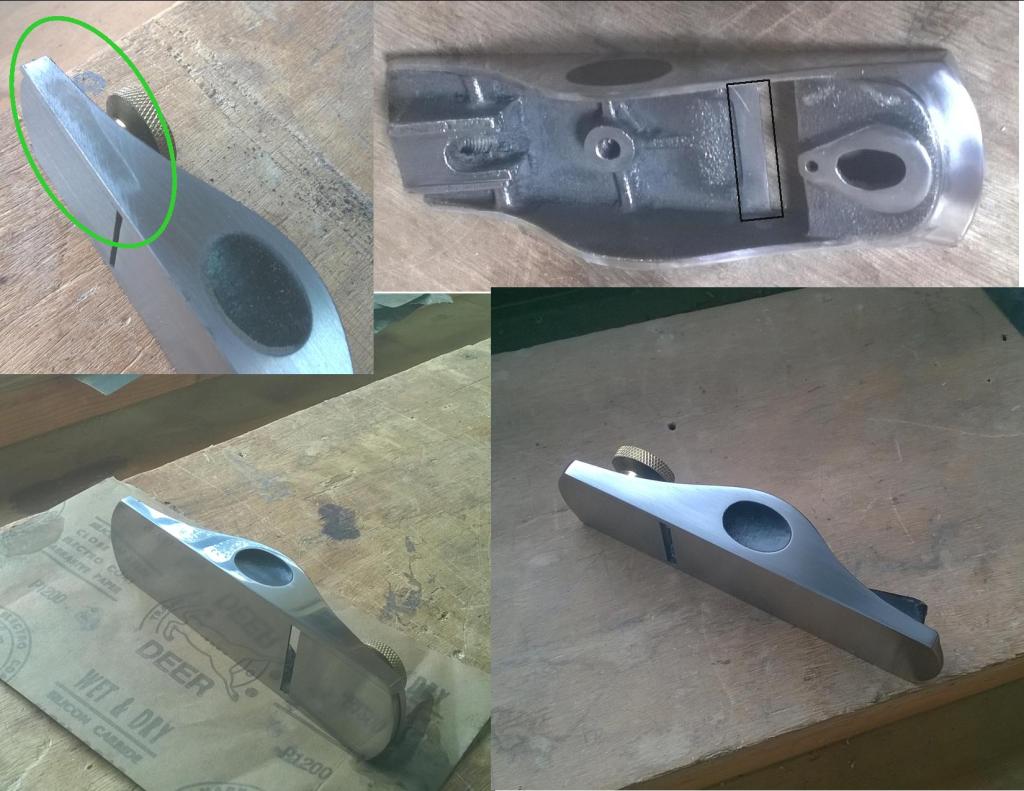
The image at bottom right shows the same side after working it with 600 then 800 grit paper. You’ll have to imagine the time spent pushing it backwards and forwards across the paper. The trick here, and maybe a point at which lesser mortals may give up, is the body must be kept flat and square to the abrading surface until all marks pits etc are gone. It’s time consuming and a nice little workout. Errors cannot be flattened in isolation as the side/sole will not be square and even. This would result in very disappointing performance and poor accuracy. Rather than being a pleasure to use the plane will become a paperweight.
Note that the front adjustment knob is in situ. This is necessary when flattening the sole but not the sides. The throat plate has to be at the same level/flush with the main sole and cannot be worked on separately. Again hard graft but well worth it. The knob and it’s threaded rod are the only parts used to secure the plate. The rest of the adjusting parts are not needed so do not fit yet. Once you have removed all marks and problem areas with rougher grits move on up through increasingly finer paper until you are happy. For example 240, 400, 800, 1200, 2000. The result using 1200 grit is shown at bottom left, 800 grit at bottom right. If you are happy with a clean matt look this may be your limit. Finer papers often show up areas previously unseen which of course means a quick rewind back to a coarser grade and then onward once more. The majority will realise that to be the case.
Avoid removing metal from the edges of the throat/mouth plate that contact the inner groves of the sole. They need to be as tight as possible to prevent lateral twist of the plate in the body. If you can hardy see the edges when the sole is flattened all is well.
What is apparent is that the smoother the surface the less moisture can take a hold on the metal. This means that a tool even in low use gathers very little rust. This plane gets used in fits and starts, utilised a lot on one job but often not at all on the next. My workshop is cold, and the damp Scottish air is not kind to my tools. Surprisingly, in the last four years this little plane has not had one spot of the dreaded ginger plague. More work now equals less work in the future perhaps? Your choice, but it’s why i tend to go the the finest grit available.
After sorting out the sides and sole the other parts needing attention were the toe – as noted earlier, the adjuster bearing surface just behind it and the top edges of the body. The mouth comes later (all at top right) You could leave the top edges and paint them. However, this would be contrary to the original goal. The edges need any dinks and pitting removed. Sanding and polishing improves the look. Paint has a habit of chipping in use and this would make the whole tool look shoddy and all previous effort worthless as the edges are susceptible to direct contact. Additionally they lead off the now gleaming front edge so it makes sense to give them the same treatment.
Applying Leverage
Now the lever cap can be sorted out. As with the body nothing can be assumed as to the state of what lies beneath that delightful original finish. You may be lucky and find little to be corrected or a horrendous mess requiring a lot of graft. I can make no promises.
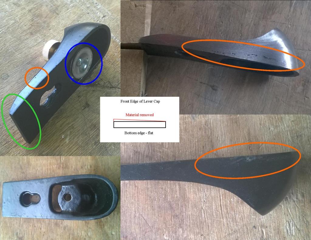
Here we go again! Top left. The lever cap as it was on the plane as new. The green area shows the problem area as mentioned earlier. The mishapen front edge will neither sit correctly or flatly on the plane iron. This will mean the pressure is not applied evenly across the width of the cutting edge. This translates into an inabiliity to produce lovely wispy shavings and and the user enduring teeth shattering chatter when trimming end grain. Not nice! This was filed down after marking a 3mm (1/8″) line up from the bottom edge and working down to meet it (centre image). Fortunately the bottom of the cap was square to the sides, rather than the top being square and the bottom wonky.
The orange circle (top left) indicates quite a deep pit which took time to remove. Quite obvious despite copious amounts of manufacturers paint. The blue ring shows one of the studs talked about earlier which holds the contact plate in place. I’m showing this to justify it’s removal. The cap can’t be properly stripped or refinished with it in place. Additionally, the base cannot be flattened to sit correctly on the iron – with the image (at bottom left) showing how unlikely that would be given the undulating surface on view – without the plate being removed. Yep! Correct, it will need flattening, although not to a blemish free surface: 600 – 800 grit is fine. It’s not on show, nor is a polished finish a requirement for functionality, just enough to sit flat and even across the Iron – ideally contacting approximately 80% + of the area. Ahh.. yet more work.
The two right hand images show both sides of the cap – top one after stripping, the other before. The pitting from casting jumps right out and shouts “Prepare for lots of work!”. It didn’t lie. It’s an awkward part to work on and I had to resort to hand files to get rid of this unsightly mess. What about power tools to get it off? I can hear it now. I felt it was easier and less likely to screw the piece up by going steady with hand tools. That may be thought of as a lack of experience or inability on my part, or it could reflect experiences in the past. The fact is that a vast amount of hand work is still carried out in engineering companies across the globe, particularly in production of high priced items. Why? Because it’s appropriate, gives better feel and it works. ‘Handmade’ is deemed desirable.
Again, after filing it’s back to working through those grits until the desired surface condition is reached.
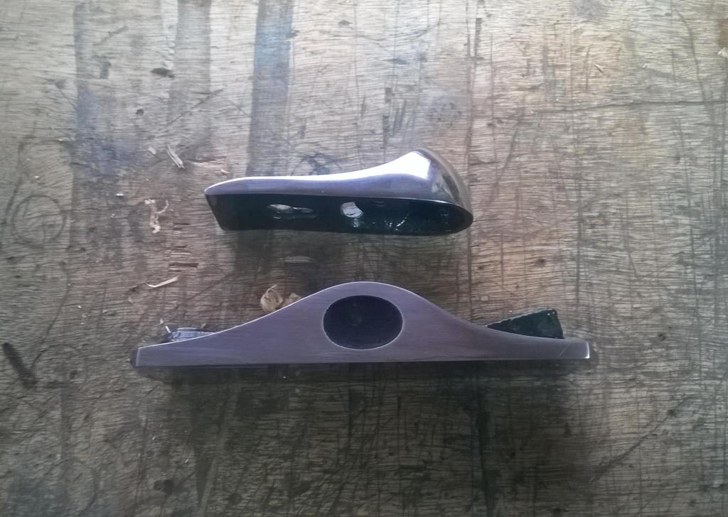
Dad, are we there yet?
Well – nearly. By now the two main parts should look like this.
So onto Part 3 – The finish is in sight.
Images and Article Copyright © 2024 by L.C McCarthy
