The usual safety provisions apply. I won’t insult the capable but for those who are a little vague on what’s under discussion please read the safety stuff on the Information page.
Battery clock to Mains power
I’ve got a nice clean dialled clock (needed so I can make out the time clearly from up to 24ft away) in my workshop. Taking an AA battery in the standard mechanism, it should tick away happily for a couple of years. Sadly, like many of us it doesn’t perform well in the cold. Winter is definitely ‘go slow’. It loses a couple of minutes daily. Batteries do not like very low temperatures. Ask your car!
So, short of shitcanning a decent clock and spending cash on a mains version, what’s the solution?
Providing constant power, unaffected by weather, from the mains sounds just the ticket!
Well, I know you can get commercial adapter kits so why not make something out of what I’ve got kicking about?
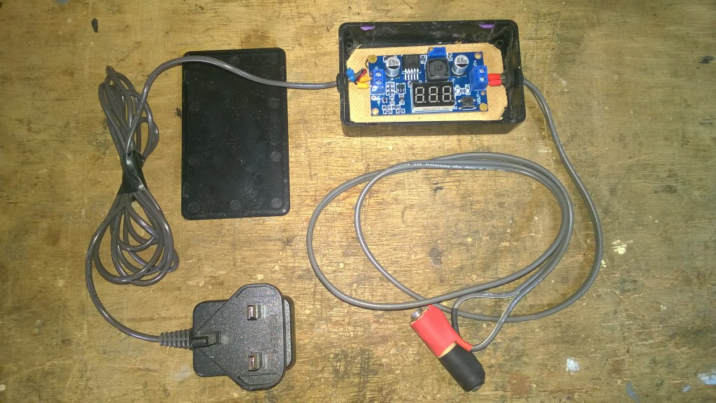
So here’s what I gathered together;
- DC to DC buck converter PCB – printed circuit board. Output 1.25v – up.
- An old phone charger or psu with a voltage of 3v upwards.
- A small project box
- A couple of feet (or what suits where the clock is positioned) of twin core cable + two (terminal) eyelets
- A small piece of 1/2″ – 12mm dowel – a couple of screws or drawing pins – Insulating tape. The screws should be less than 20mm long.
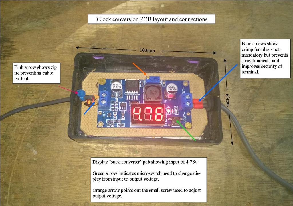
Top to bottom – the pcb’s are available at Jeffy ‘B’s online emporium. 2 types – with or without lcd voltage display. The display ones I’ve had often won’t show voltage under 2 volts (?) However, they do go lower and attaching a multi meter to the output solves all. Therefore the type without display are fine if you’ve got a meter. They are only in couple of pounds each, the display types cost £3-ish. A meter will pay for itself in a few jobs.
AA Batteries – rated at 1.5v. Also known by its dimension 14500 (14mm x 50mm – particularly with rechargeable cells) The power per cell is dependant on load – capacity is obviously effected by what is drawing the power but it also impacts voltage. This means it drops. Rechargeables are rated at 1.2v which is more constant. I picked a point halfway between the two voltages. I could cover this more but space does not allow, plus better people than I provide explanations online.
I’ve used a few old chargers/psu’s for this type of project. Input voltage needs to be higher than your required output but the majority will easily do the job at over 3v and up. Ampage – amount of power being delivered if you like – may be small – 160 milliamps/0.16A in this case – but this is way more than an alkali AA would need to provide for the clock.
As can be seen from the image the pcb itself is clearly marked – input, output, positive, negative etc. The input voltage is displayed but cannot be adjusted, and why would you? The output is the concern here. The only thing it confirms is you have (the stated) power coming in, i.e the psu works.
Project boxes are small plasic or metal boxes with lids designed to hold pcb’s, fuses, and other components/assemblies. Numerous packs and sizes available – usually a couple of quid or less each. The pcb in question has room to spare in it’s new home (see above).
Twin core, or two single cables if that is what you have. This does not have to be thick or heavy. Bell wire or speaker cable is fine. Again, the power demand is very small.
All the rest is fairly self explanatory. So what do we do with this stuff?
Strip whatever outdated equipment plug (e.g mini usb- branded plug etc) is present from the end of the charger. Do not plug in. Spend a few moments reminiscing about the phone this weirdly shaped piece of plastic used to serve, chuckle and shake your head. Make two holes – in each end of your project box – and thread bare end into box. Identify negative/positive and attach to board as seen in the image above at left. Take other piece of cable and put an eye on each end, thread other end into other hole and secure bare ends into output terminals. Note/mark which is pos/neg.
I’ve attached the board to a piece of hardboard with small screws, which is then fixed into the box with double sided tape. By all means use standoffs or similar. Stopping the pcb rattling about is good practice, and prevents damage.
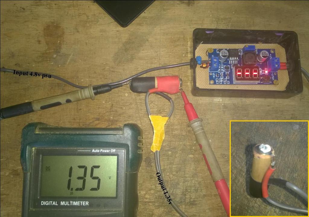
Attach multimeter to eyes (alternatively you can test at output terminal on the board without wires attached). Plug in charger. See what output your meter is showing. Press microswitch to change display to output. With a small screwdriver adjust the brass screw on top of the small blue ‘box’ down to 1.35v or thereabouts. If you put too much more, 1.55v for e.g, it’s likely your clock will run fast. Mine did, I tried it to see if that happened. Unplug from mains. Don’t fiddle with board further.

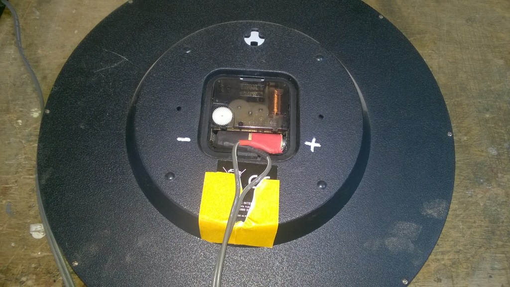
Take dowel and cut to length of AA battery minus 2mm, or more if you are using screws. Mark the centre of each end and fix one eye either end with pin or screw. Tape the wire down using red for pos if possible, and black for neg end. Insert into battery compartment, plug in charger and watch it run!.
Total cost – £4-5/6$ – Job Done!
