A couple of other small ‘bits’ worth mentioning
(which I can add to as stuff crops up..)
While I was going through a couple of outstanding jobs for this piece I came across a fault that I’d had once or twice before and I thought might help someone out
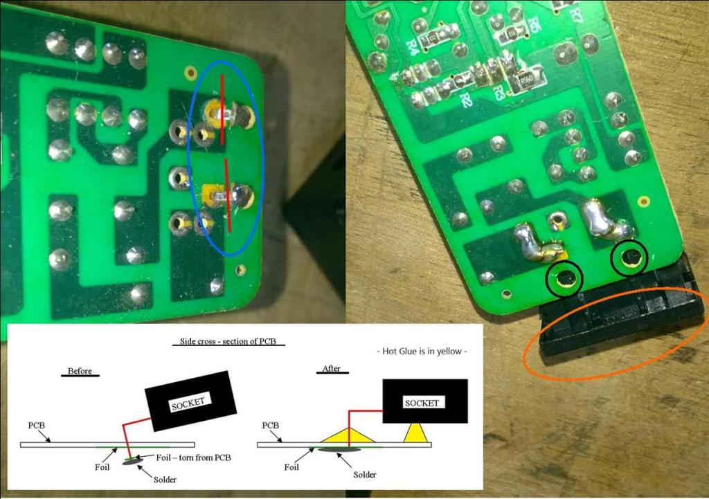
At left above is the failure of the join (blue ring) of the mains socket (IEC C14) where it attaches to the board. The contacts have been soldered onto the conductive foil of the PCB. This foil is not structurally capable of supporting large components, it’s only microns thick! I suspect the two holes- ringed in black at right – might have been intended for this purpose but not used. What has happened is the unit has been knocked or dropped and the shock has torn the contacts free of the foil (red lines) and current no longer flows. The board was not fixed in the casing and was capable of movement. Really poor build quality, on the cheap.
Re-establishing contact by connecting back onto the same foil, or it’s associated contact points, will solve the problem. Hot gluing the socket to render it immobile would be good.
It can be seen on the right a couple of minutes with the soldering iron has solved the issue. I’ve soldered onto two of the closest points to increase mechanical strength. Suffice to say it worked…
Equipment Power problems
This small bit is just to connect what was covered on page 2 to actual equipment. Most will have noticed that there is a voltage change theme going on here. Some items need a DC voltage input requiring a suitable external power supply – as above. Many larger items have the same requirement, but come with the board already built in – enabling items to be plugged straight into the mains.
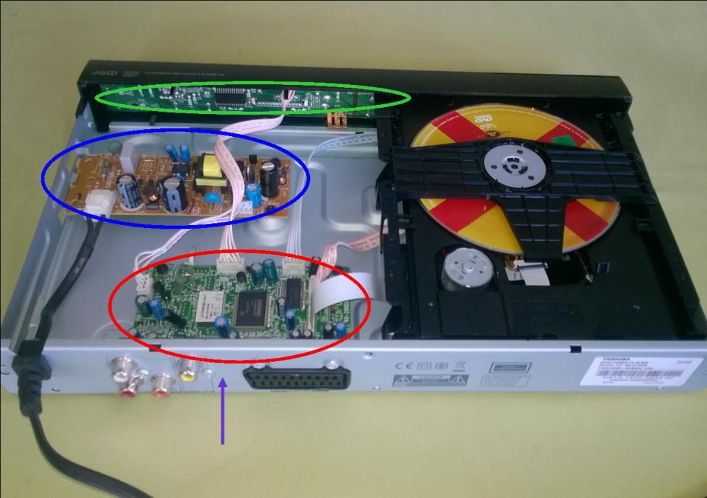
The image above shows the interior of a Toshiba DVD player. I’ve no doubt this was less than £40 new. As the more astute will have noted the blue area contains what looks very much like the sort of PCB already discussed. Maximum points for you. The mains (AC) cable coming in is also a clue.
Power (DC) leaves the board via the connector at bottom right of the board by the light blue capacitor. The (red ring) board it feeds is the main board which, unsurprisingly, is where everything connects into; Scart, RCA (video, audio), digital coaxial audio. Various leads can be seen feeding the display board at the front – ringed green – and the disc unit.
The point being the board suffers from similar failures to the plastic boxes, and this is where I find a lot of capacitors of insufficient value – the ’10v – 12v’ bit from earlier. I’ve dealt with more in smaller units such as freeview boxes. The confined space ups the heat, and if the unit is located in a confined space, it’s death is only a matter of time. It should be noted that some boards may have a fuse – in a spring clip or soldered in – and that can be replaced. This was common years ago but seen much less these days – reflecting the nature of our consumption habits.
It’s very convenient for the manufacturer to swap boards out under warranty, or change them for regional voltage needs, so access is simple. As I’ve said this type of board arrangement is pretty common. Manufacturers like to give the impression that they all have differing technology, which in certain areas is true, but there is a lot of commonality in components and build style/layout.
Some may have made the connection between the unit running on 12v power and the fact that your PC does the same. I stripped a LG dvd recorder a couple of years back that contained a disc unit that would have slotted straight into a home computer without any problem – same power and data connections. The landscape is not as complex as might be portrayed.
There’s very little to lose in opening up the item. It may be you can see the damage, but at least the layout will be familiar. It goes without saying, but I will, that it might be a more complex failure. Nothing really lost bar a few minutes. But a victory may be gained!
Images and Article Copyright © 2025 by L.C McCarthy.
