The usual safety provisions apply. I won’t insult the capable but for those who are a little vague on any activities under discussion please read the safety stuff on the Information page. For info related to batteries refer to the battery main page (if it’s not down for editing).
Introduction
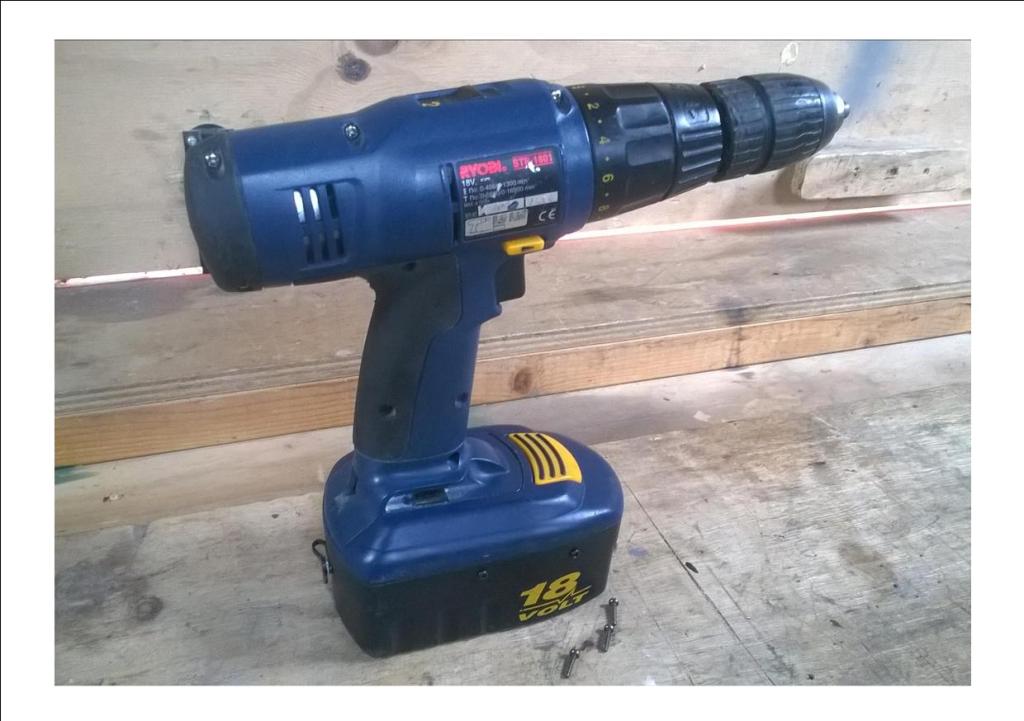
Like many others I’ve got quite a few power tools that are unusable because the antiquated Ni Cad batteries won’t take/hold a charge. The tool in question that requires raising from the dead is an 18v Ryobi Drill. This is twenty two years old with a fine quality chuck and gearbox. The motor is sound and all the switches and other components are good. I split the case, cleaned and checked everything, and put it back together. These blue Ryobi tools were pretty decent 20+ years ago. I own a few – reciprocating saw, low angle drill etc.. – and the plastics and build quality were quite good. They’ve all been well used – as can be seen by the drill’s chuck. This one cleaned up well for it’s age – I’ve seen rougher 22 year-olds.
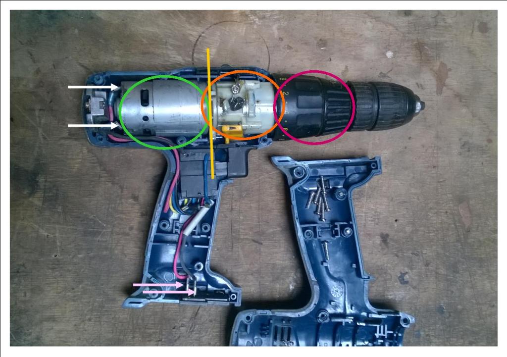
For information: above – I’ve just opened the case to briefly describe the drills basic components. The green area is the motor itself. These have common sizes. Many have variable voltage and the tools power is dictated by voltage (battery) input rather than the motor itself, in other words the same motor may be in a 10.8v or a 14.4v tool. Often the motor is marked with data, enabling a replacement to be sourced but not at inflated brand parts prices. The white arrows indicate input terminals + and -. At the yellow line indicated the assembly is likely to split into two. This is OK, it’ll just go back together so don’t worry. You will see a cog on the output shaft of the motor: if you are fitting a new motor make sure the size/teeth number match any replacement as this interfaces with the gearbox ringed in orange. Not matching these parts together correctly will be unwise and result in a fail. At the top of the gear box is the plastic speed selector switch so remember to put it back when reassembling (visible near top of yellow line to the right).
The area ringed in magenta (nice!) is the mode selector and torque mechanism. Leave it alone if possible – it’s normally full of small parts that resent being taken apart and refuse to go back together, in my experience. The whole drive assembly – motor, gearbox, chuck, etc – can be gently lifted out and laid to one side, carefully removing the direction switch and trigger unit plus all the wiring – without disconnecting anything, unless you’re replacing the motor. The pink arrows show the battery connections leading to the trigger. Take a photo first for reassembly purposes. Now put the bare case in the sink and scrub away inside and out! Dry. Wipe down drive assembly and re-grease as necessary. Reassemble. A treatment for plastics – i.e car dashboard cleaner – will improve the outer case appearance, errr…probably!
Tip – You can check the tool by using another DC source (battery or PSU) of the same spec and a couple of test leads. A quick contact should prove function, or not! Don’t keep the circuit live (press the trigger) for longer than the second or so needed if you use the thinner test leads. The high resistance tends to make them hot. If it looks, sounds, and smells okay it most likely is. Yes, Smell! If an odour comes from the tool, reminiscent of the time the kids demanded a funeral for the Hamster, that included a cremation, it will need further investigation. They don’t hibernate do they?
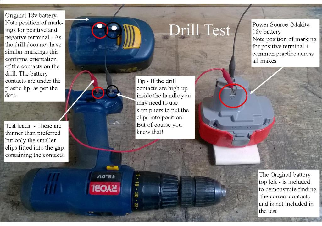
One of the solutions I’ve carried out is to replace the cells inside with a more modern lithium alternative. A pack can be built, and sometimes (in a difficult area such as a unique or rare battery) this is the only way, or another battery can be stripped for a donor pack. I’ve utilised the latter here as the original battery case is large and a pretty uniform shape.

Mission -if you chose to accept it – is to install a modern power pack, attach it to the existing tool power connections, and add a remote charging point to the original battery case.
Question – Will a 18v lithium battery, like you describe, really run a tool that originally had a different battery technology? Yes, it will. (Otherwise you could stop reading here. I appreciate that some content on this site is made up for humourous effect, but rest assured this article isn’t. Some claim the rest of my stuff isn’t funny either but I’m okay with that, or so my therapist says.)
Going online I searched around on ‘Jeffy B’s Online Emporium’ and found a Chinese cordless chainsaw with 18v (5 cell) packs suitable for my needs. I got 2 batteries and a charger – plus two spare chains, and a bar, for my other saws, and some other stuff that isn’t relevant here (20+ quid of spares if bought separately) – for £26 ($30) . Add to that the few little bits* below and it means you’ll get two new batteries plus charger for your drill for less than 30 quid.
- Donor batteries and charger (as discussed)
- Soldering iron + solder
- 1 x DC socket connector – female barrel plug (ensure it fits the charger)*
- A couple of spade connectors – 6mm or 1/4″ plus 2 short lengths of suitable wire 4″/100mm*
- Tools to strip the battery down; driver to fit, usually Ph1 or T10/15, plus pliers etc
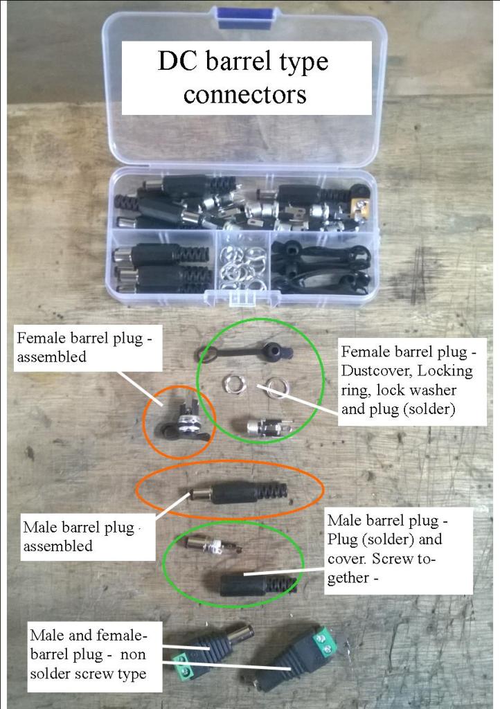
In the above image I’ve shown a couple of options for you to consider when collecting your parts. I’ve only fitted the female socket not the male part, as you’ll see further on where you can fit the male plug – Your choice. The best option is to solder the wiring – I’ve used 24 awg – and plugs together. Not only is it more physically secure it’s better practice as far as the passage of current is concerned. The bottom type with screw terminal connectors (the green plastic area) are great for making temporary cables or static connections in protected locations, but personally I would not use them in a permanent moveable role as they don’t have the physical strength or defence against spills, damp, dirt etc that fixed items do.. The female plug should ideally be panel mount, that is permanently fixed into a precisely drilled hole and locked into place (see final images). The screw terminals type at the bottom would have to be glued into place – not the ideal solution. I am not aware of a panel mount with screw terminals connection, only solder – and I have looked! An alternative, if soldering is not an option, is to buy both parts with tails (soldered wires) already fitted and make (crimp together) a ‘cable’ to fit: worst case scenario fit a panel mount female with tails, and a screw fit male to the other end.
*You’ll need to get the right barrel connectors for the charger. The standard size that I’ve encountered is 5.5mm outer size – a really common one – however, there are two internal pin sizes – 2.1mm and 2.5mm – I have chargers/batteries with both sizes. You can make all conversions a uniform size by replacing the plug as it will not impact function whatsoever, if you wish. Replacements are very cheap too, unlike the original branded chargers (if you could always/still get them that is).
Read on. Trust me – it’ll make more sense with more images to come.
Get on with it!
Open up the old battery case. The top of the case (tool interface) will be attached to the cell pack by at least two wires. Cut them as close to the pack as possible and remove the old cells. I have never found these to be held in with anything other than friction.
A couple of further options that could be considered – Firstly. Could I have reduced the size of the battery case as I had more than twice as much space as needed? I suppose less bulk and a more modern streamlined look would be desirable. However, I didn’t think it was needed – I’m looking for a working tool not a fashion statement. I would have needed to cut the bottom off the case, reduce the height and replace the bottom, all with an uncertain outcome. Not all cases will permit this due to shape, plus I’m keeping it simple. The result will be much lighter and the original battery profile will keep it stable when stood up. Secondly. I could have doubled the size of the pack – see Battery page i.e. series and parallel – for more longevity (amps). This is a good option but I’d have needed to butcher the other pack and you’ll end up with only one battery pack. Obviously swapping and charging is more user friendly with two batteries -that’s if you originally got two NiCad/NiMH with your tool to convert. Most decent brands – apart from ‘diy’ ranges (such as Bosch Green or cheap Superstore specials) – do two batteries, cheaper ones not so much, as the battery is a high cost item. Modifying the case – as discussed above – is going to prevent any future size expansion.
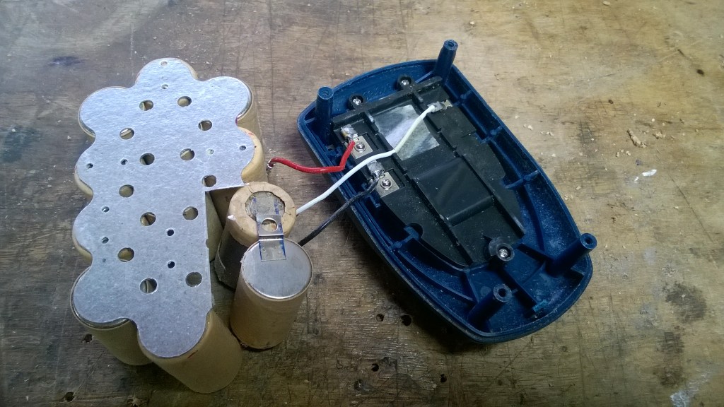
Here is what you’ll typically find. The red and black are the positive and negative respectively, and closely follows the image above when we tested functionality. The white lead is for the sensor/thermal fuse which normally communicates with the battery charger. Not needed with this project. Dispose of old batteries per local advice.
Note – More modern chargers for lithium batteries are simpler and lighter than older chargers for Ni Cad and NiMh batteries. A lot of the diagnostic tasks are now carried out by the circuit board which is part of the battery pack itself (see below image). Hence the lithium charger is really just a power supply/transformer.
Fitting the donor battery
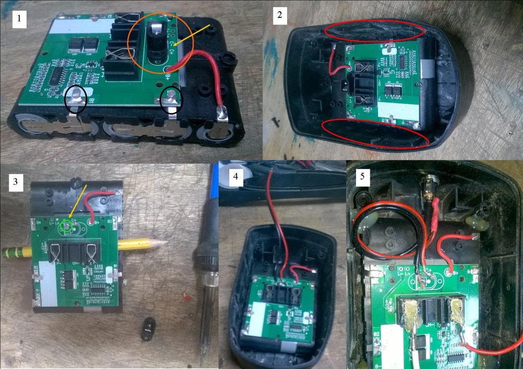
Here’s the donor 18/21v 5 cell pack, sans* case – 1. I’ve ringed the DC input in orange. It’s vertically mounted which is challenging for fitting and charging after the conversion. The yellow arrow is indicating the PCB markings for the pos and neg connections. 2. Fitting your pack into the case is the first job as it’s position will impact all the steps that follow. The red areas mark where I’ve had to remove plastic case ribs that held the previous cells in place. This also meant that the lack of space across the case bottom indicated that the screws (holes) holding the battery case closed were now redundant. More on that later. 3. I’ve removed the DC input as I need to reorientate the charging pathway from the top of the battery. The pencil is giving me a gap to desolder the socket from the underside of the PCB without removing the board (tabs) from the cells. You can see 2 of the relevant tabs in pic 1. – black circles. There is enough give in these to make a gap to get the soldering iron tip into. I put a small flat screwdriver under the socket, where the yellow arrow is in pic 1, to help lift it away. I’ve ringed in green the resultant negative contact point, the pos is at 2 o’clock from the neg.
*very cosmopolitan or pretentious twat – your choice.
Pic 4 shows where I’ve soldered ‘tails’ onto the aforementioned points. I’ve left them long so I can access the pack at a later date without removing the socket as the space allows for that. As mentioned above you can attach a male plug – if the socket had been horizontal I would have: instead of soldering – giving the ability to remove the pack intact if repair is required or swap out with another pack. Last pic (5) shows the pack hot glued in place at each corner. This has been nice and secure for general workshop use, but if you’re going to throw the battery at children, the dog or a neighbour a bit of firm foam will provide extra support. I don’t have a dog so I’m happy to leave an air gap, although the pack does not get hot at all. For the safety considerate the pack has considerably more circulatory thermal ‘elbow room’ than the original case provided.
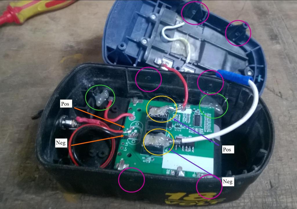
The socket is in place at the rear (left). That takes care of the pack placement and charging facility. We can now address the means by which power reaches the tool. As we are using the existing tool interface and the relevant connections are already identified we now need to connect the pack Neg and Pos to the one coming from the battery ‘top’. The pack terminals I’ve identified with purple arrows in the above image. If the markings aren’t good/clear, or you just wish to confirm, you can use the test method above (tool + test leads to check viability) or a multimeter to determine polarity. I’ve extended the neg lead (white) to allow better access – btm left – both have Lucas blade/spade connectors slid onto the pack terminals plus I’ve hot glued them into place for security.
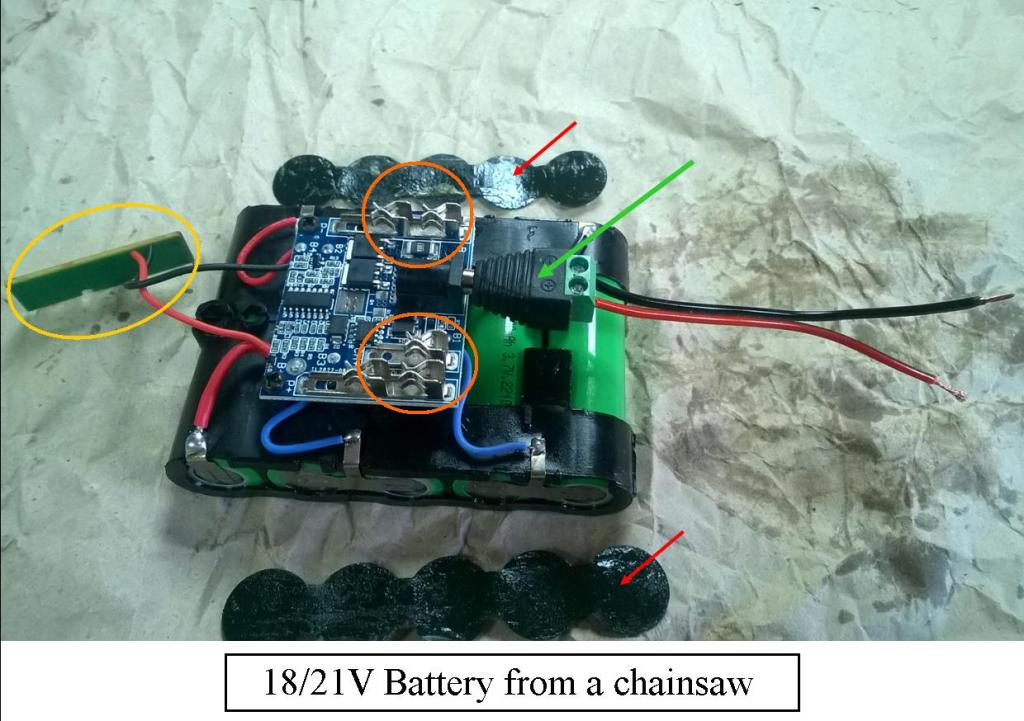
I’ve added the image above to show the slightly more practical battery pack with a horizontal charging plug. The plug – green arrow – is the screw type and the ‘tails’ are fairly short as the pack can now be unplugged for removal. Therefore longer wires giving ‘freeplay’ are not needed. These would normally be connected to the external case socket (see 4 below) but that’s not shown here. The power connectors ringed in orange are perhaps a little more accessible (open) and soldering would be an option. The small PCB circled in yellow is the battery charge indicator as seen on many batteries. You could modify this and affix to the outer case. I wouldn’t bother as, although these bits always seem like a cool idea, nobody really uses them. It runs, or it goes on charge is the usual scenario. I’d just tuck it into the case, or if stuck for space remove it from the board.
Note: It’s worth noting that this battery is from a chainsaw, a tool that uses – ideally – oil for it’s functionality. Many will know that oil likes gravity, but also defies it quite often and finds it’s way into places you don’t want it, like inside this battery. The battery terminal insulators arrowed red (aka bits of black tape) have come away and the pack was plastered like an Amoco Cadiz seagull. Oil was wiped off and everything was fine. Just thought I’d make you aware as it takes only a couple of minutes to clean away, and may pay dividends later..
And Finally….
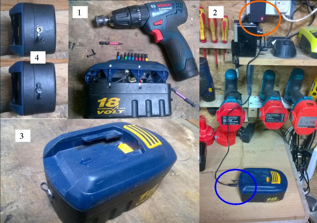
- As mentioned above I couldn’t use the original screw holes to close the case. Instead, using the original T10 screws, I identified the old fitting points (marked with white dots) shut the case and drilled through both parts at once. Said screws were inserted. They did not foul anything internally, but it may be an issue so check. Perfect.
- Showing the finished item on charge. The charger is happy. It doesn’t know the battery pack has a ‘new coat’ and it doesn’t care!
- As can be seen it would have been problematic to charge the battery with the original vertical socket as the tool slides into place here. I could have thickened the surface and drilled a recess into the plastic to get clearance but here’s no point. It would hide the socket but lets keep it straightforward hey? Less hoops to jump through is good in this case.
- And as this looks neat and tidy, and works well, keeping it simple is the goal.
I hope this may help getting a golden oldie or two back into use – all viagra related matters go under medical advice, not here! Again, it’s all about resolving problems, achieving, learning and fulfilment. Thanks for taking the time to read this.
Images and Article Copyright © 2026 by L.C McCarthy
 L C McCarthy