Although I’m a trained electrician – an appliance repairman I freely admit I am not. However, I am a problem solver by nature and, as long as common sense is applied, I believe we’re all capable of much more than might be expected. It could be said I’ve had a fair bit of experience on this side by side fridge freezer.
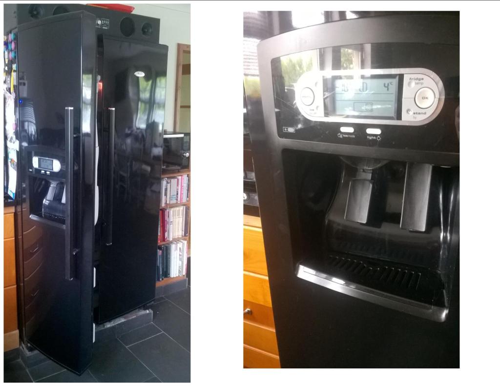
This is the fellah in question – A Whirlpool S20BRBB20 series unit. A lot, I should say a very high proportion, of the parts in this appliance are common to many other makes*. Many of the parts discussed in this article are widely available online. This could indicate they have a high failure rate and/or appear in many different models and brands. Unfortunately this doesn’t translate into high volume equals low cost!
*This defrost element fits Whirlpool, Admiral, Ariston, Bauknecht, Hotpoint, Indesit, Maytag + others. (similar models of course – not everything!)
I’m going to discuss common faults on this model of fridge/freezer relating to my experiences with the defrost facility and hopefully, by giving an overview of the parts involved, help in the repair of this otherwise great appliance. In describing the symptoms it must be realised that there may be a host of reasons why certain conditions exist, not just the one under discussion. However, a little investigation indicates what I’m dealing with are very common faults and the parts sales seem brisk. The faults under examination are:
- Element failure
- Thermostat/Fuse failure
- PCB (rear) repair
What’s gone wrong?
The high temperature alarm has gone off. The fridge is too warm. Icemaker is not playing ball. The frozen food is defrosting despite being caked in solid layers of ice! Yep, it seems the defrost cycle is not functioning. The defrost element is not …errr..defrosting. Why?
- The element itself is duff/ knackered/kaput.
- The thermostat array has died, shuffled off this mortal coil, is no more.
- The control board (PCB) has a bad component(s).
- There may be a fault with wiring or connections. Unlikely as the quality is pretty good – barring the likes of rodent damage or physical force; nipping, trapping or pulling of wiring.
Note: If your appliance has tripped out – i.e current is ‘leaking’, and you cannot reset with the fridge plugged in (i.e the RCD) – this may well point to an element failure. Thermostat failure means the thermostat stops opening and closing and often nothing else damaged. If it fails while open, current cannot pass. Basically it’s switched off somewhere you can’t access
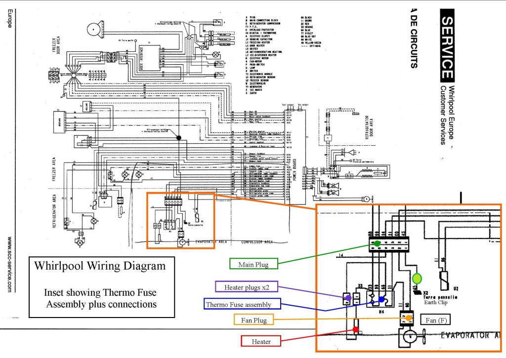
Hopefully the above diagram will help to clarify all the various parts involved and I’ll use the colour coding to tie it all together, i.e – the heater plugs in every appearance are always purple. It looks complicated but just following each line simplifies the method of operation. We’ll only be looking at the inset but it’s just lines and components. No sweat.
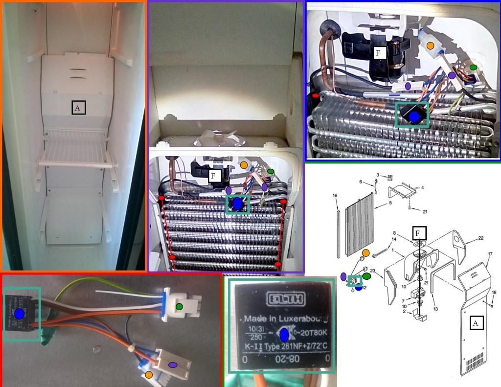
Top left image shows the freezer compartment emptied. Cover ‘A’ is held on by a handful of PH2 screws. For orientation the fan is directly behind the letter ‘A‘. Remove all shelf brackets. There’s a plastic shroud at the bottom of the cover that’s not shown on the bottom right diagram but it’s just another four screws. Air is drawn up here and flows across the EVAPORATOR – the big shiny bit that makes everything cold – through the fan ‘F’, then travels upwards to serve the ice maker, and a small vent at the top of the compartment that feeds into the fridge side to provide it’s cooling function.
Centre top is what’s underneath cover ‘A’. The main aluminium matrix is the Evaporator and the copper pipes feeding it with compressed gas are clearly visible. What isn’t visible is the heater element but it runs down a channel on each side of the Evaporator as indicated by the red lines. The purple dots mark the plugs that carry current through the element.
Top right is a close up showing the Thermostat/fuse/junction unit – or Thermo Fuse. This should be clipped to the pipe immediately below the fan (blue line). I’ve moved it for clarity. Bottom right is the parts breakdown for the area contributing to a more complete picture. The lower centre picture has a close up of the thermo fuse if anyone wants to confirm/ check the specification of any part ordered. Finally bottom left mirrors the plugs and wiring shown in the wiring diagram. The green heatshrink is on the end of an earth clip that attaches to the evaporator. What I’ve tried to do here is to link the wiring diagram into the physical appearance and then back into the parts breakdown diagram in order make a clearer picture when you’re actually working on the appliance. I’ll be referring back to all these images later.
Element
I’m not going to bog down the narrative describing how to test an element. It’s pretty straight forward and others have described the process at length (even though it takes less than a minute). You’ll need a multimeter but at £10 online it’s an investment. You can test for continuity using a simple circuit workaround, but it won’t rule out all conditions. Continuity doesn’t mean the element is working or safe. The internal wire may be broken but touching the inside of the outer casing causing a short. Testing resistance is a better test and, as with continuity, it’s very easy and advice is freely available on You Tube etc. If the outer casing is damaged or obviously burned it’s clearly had it – this will trip your RCD.
If it’s trashed a replacement is the only option. The last one I bought was around £40 ($50) – IIRC, but many charge £70 and up. Still cheaper than someone coming around your house 3 days after you called, humming and shaking their head, leaving your appliance in bits on your floor and returning ten days later – after the family has tripped over the parts navigating the necessity of the kitchen – to fit the part and charge you £450 for the pleasure.
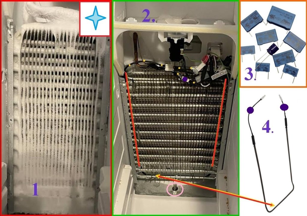
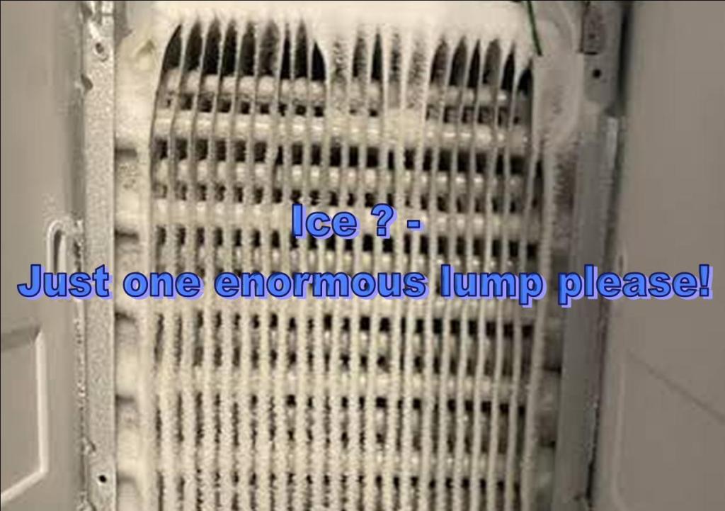
Above 1. If it looks like this behind panel ‘A‘ you’ll need to defrost before you can start work. I’ve marked this image to reinforce that fact. Yes, there are those who think they can bypass this step, however there are delicate assemblies and components involved, so go easy. That goes for handling the replacement element. Going 14 rounds WWF style (I think it changed it’s name but fighting a Panda would be similar) with the element will end in tears, but without any bamboo related injuries.
2. Again I’ve identified the element pathway and referenced it to the actual part at image 4. so you can see it in place. The pink ring at the bottom is for drainage of waste. I expect that’ll be easy to remember. Make sure it’s not blocked as that’s problematical. Note: a small pipe leads off to a tray underneath, and heat from operation will help to evaporate any fluid but NOT frozen peas and the like.
3. Is the capacitor set discussed on page 2.
The multi meter tests can be carried out in situ, so no need for removal. If it is knackered you’ll have to remove the screws holding the Evaporator against the back of the compartment. You can’t remove it completely because the feed pipes up top cannot be disconnected. . If you didn’t remove all the shelf brackets earlier, at this point you’ll wish you had! You can see from the image above that the bottom of the evaporator will need to swing towards you (45 degrees or less if possible), and needs a clear path. The element can then be slid out via the bottom, freeing it from the clips holding it in place. Obviously you will have disconnected the plugs up top! Replacement is a reversal of removal, fiddly but not too difficult
Thermo Fuse (Thermostat and fuse assembly)
This is the cluster of wires and a small black module (the blue dot item – also outlined elsewhere in pale blue). In this model it is incorporated into a fuse, thermostat and wiring hub assembly. The fuse prevents the element going nuclear if the thermostat fails. Rather than have external connections for the various circuits they are incorporated into one sealed unit. Given the temperatures and moisture involved and the way materials move at temperature this is supposed to prevent early failure with those factors in mind. It’s a unit sealed with resin and therefore almost impossible to repair. Often in other models the thermostat is separate and can be replaced independently, but not in this case. Ditto for the fuse. So it costs more to fix – Surprised? I thought not. I have in the past made a short term fix/bypass by cutting the thermostat wires (x2 – 1 in, 1 out ) and soldering/crimping in a standalone unit of the right range.
This Thermo Fuse unit (outlined in blue dot/pale blue below and in images above) will need to be removed for testing. Simply unclip all connections – including the main plug on the back wall (marked green). Take a photo if you wish to double check the reconnection points. Testing of the thermostat function is by heating and cooling while attached to a multi meter and seeing if it switches on/off. It may be always open or always closed – which means it’s a dead item.
The fuse is tested by meter once more. If we look at the inset in the wiring diagram we can identify the assembly (blue dot). On the right we can see a twin feed – one (angled) going to the fan, one going internally through the squiggly fuse then out to a heater plug. By putting a multimeter probe onto the twin feed wire into the assembly – either using the main plug or fan plug – and the other onto the heater plug.
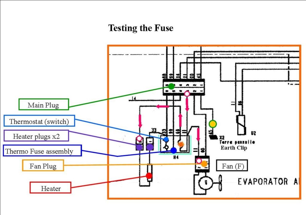
It’s not as complex as it sounds. The pink arrows above show the current path. The pink circles show testing points. The left hand heater plug is mandatory as it is ‘on one side’ of the fuse. Either of the wires marked ’11’ is fine as both are on the ‘other side’. The little orange explosion shows how a failure would interrupt your meter/the current and therefore have no continuity. As a fuse is a built in ‘weak point’ this is where excessive heat caused by an element unable to turn off (thermostat broken in closed position) would strike first.
As can be seen the current then flows through the heater (element) into the unmarked plug returning via the wire marked ’33’ which feeds into the thermostat. If this was open the current cannot flow through the element. As stated, if open through damage = no defrost!
Replacement is the only viable option – I think the last one cost about 60-70 quid. Nations may vary.

