Cont’d
Now we get to the last part of this item. The first two are not properly repairable but the PCB is. If you go looking online at a Brand dealer or stockist some of these PCB parts are massively expensive. This is blatant profiteering by fear. Here’s why;
- When designing an appliance if a pre existing board (first choice) is inappropriate, a specification is sent to a subcontractor to produce a suitable item. The subcontractor will use freely available and proven components. They will not design and produce a specific part that undoubtedly already exists. At how much cost!? And what’s the point?*
- The parts need to be widely available in order to be on hand for repair and maintenance so the brands/dealers engineers can fix your appliance promptly for a
highreasonable price. - Low cost is advantageous if you are buying thousands and banging on a huge markup. That’s good business.
- In order to ensure maximum return they will not make any of the above clear. What they often do is rename the item in literature with a new technical description, assign a different part number, repackage it or change the information on the part. All of these tactics are designed to make you doubt what you truly believe the part to be.
“It’s got webbed feet, a beak and it goes ‘Quack’.”
“It must be a duck then!”
“But it hasn’t got the right logo on it.”
“Oh.. so it’s not a duck then…. but it is!….. but maybe it isn’t…? “
“You’d probably better get the really expensive one with the branded logo on.. Just to be sure…”
*Some manufacturers do create specialist parts – and specialist tools to service them! – in order to prevent external agency repair, then provide a single hugely expensive ‘no other’ option, thereby establishing a parts monopoly – common in the car industry.
Okay, let’s look at how we can simply try to diagnose any defective parts on the PCB. Dig that multimeter out, we’re going to need it. Unplug the appliance if you haven’t already.
Removing the main PCB isn’t difficult, especially if you have access to the back of the appliance. If you were changing the PCB out completely you’d need this access, so why not see if it’s fixable first? The white plastic box at lower right tucked inside the frame is released by a couple of Phillips screws. Flipping up the cover reveals four plugs attached to the edge of the PCB.
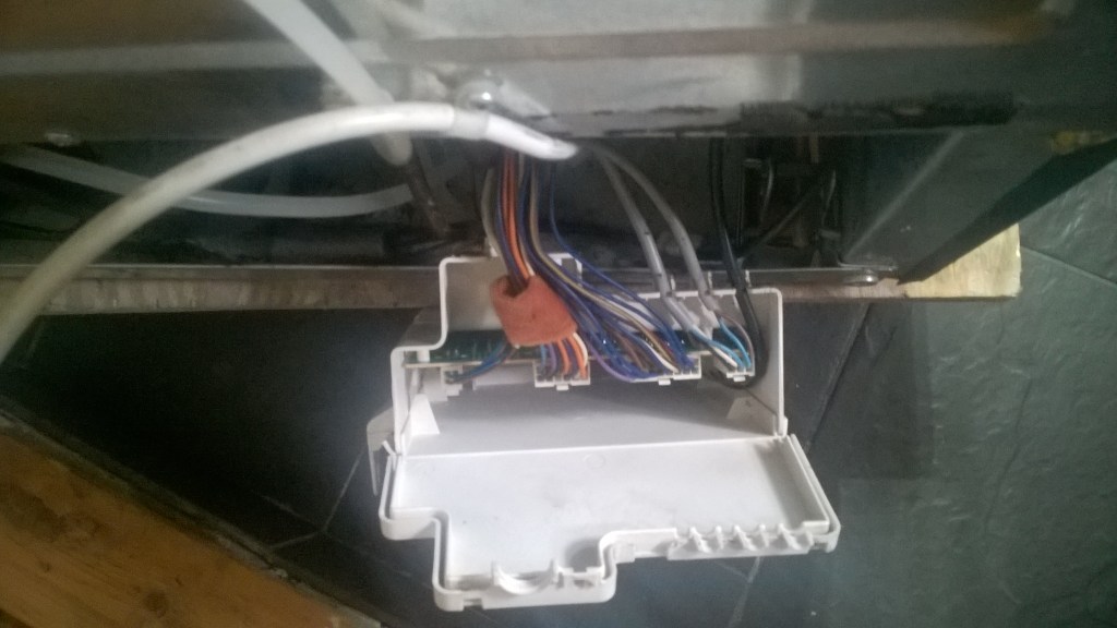
Image above – You’ll perhaps notice the colours of the wires on the plug surrounded by orange foam matches the ones on the thermo fuse previously discussed, and they look like they go up the back of the appliance and into the area we’ve just left…. Just sayin….’
Testing the wiring
(From the thermo fuse socket inside, then around the back to the PCB)
The wiring is, in the main, protected by the metal cover on the back of the appliance. However, this doesn’t rule out rodent damage, or an odds defying incident that shorts the wiring against the metal cover i.e caught, trapped or abraded.
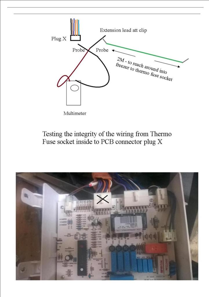
By attaching a long single core test* cable to one of your multimeter probes and attaching it to one of the plug** pins inside the freezer compartment you can test each conductor. The other probe goes to the same coloured conductor on the plug which you’ve just pulled off the PCB . Just switch to continuity. Again resistance testing is preferable as bare wires still have continuity.
*e.g 2 metres with a crocodile clip on each end – this can be made up for a few pennies. Alternately packs of test leads can be bought online cheaply – perhaps 10pcs x 50cm for a fiver? – and linked together for the required length. Multiple uses too. As the appliance is unplugged the test leads only need to take the low current supplied by your meter, and are therefore pretty thin. No problem – that’s what they’re designed for.
**To remind you it’s the green marked plug that sits back top right.
If every check ‘chimes’ you can confirm (ish) there is no internal damage to the wiring. If you have no means to make or buy the cable skip this part. As stated it’s possible but unlikely the wiring is damaged here. If you can, it’s good practice to work through logically to form a complete picture. You may wish to move straight onto the board if you suspect, smell or notice damage. However, if the damage has been caused by a hidden short in the wiring, repairs will be useless. So if you can – do. If you can’t the odds are probably still in your favour. Crack on!
Where are we currently?
- Element – Checked or replaced – All good.
- Thermo Fuse – Checked or replaced – Ditto
- Wiring – Checked and confirmed as working.
- PCB – Checking now…………………….
Remove the PCB from the plastic box – it should pop out easily. Note; only with very expensive diagnostic equipment can circuits be checked without removing components. They need to be tested off the board in isolation by mere mortals as poorly equipped as myself. Often damage is obvious and the hunt is over quickly. In order to cut down on work I tend to check the common fail components first, such as capacitors, and go back to the less likely ones. If the fault has an online ‘history’ that is a great help (such as capacitor failure for this item). Follow those leads first.
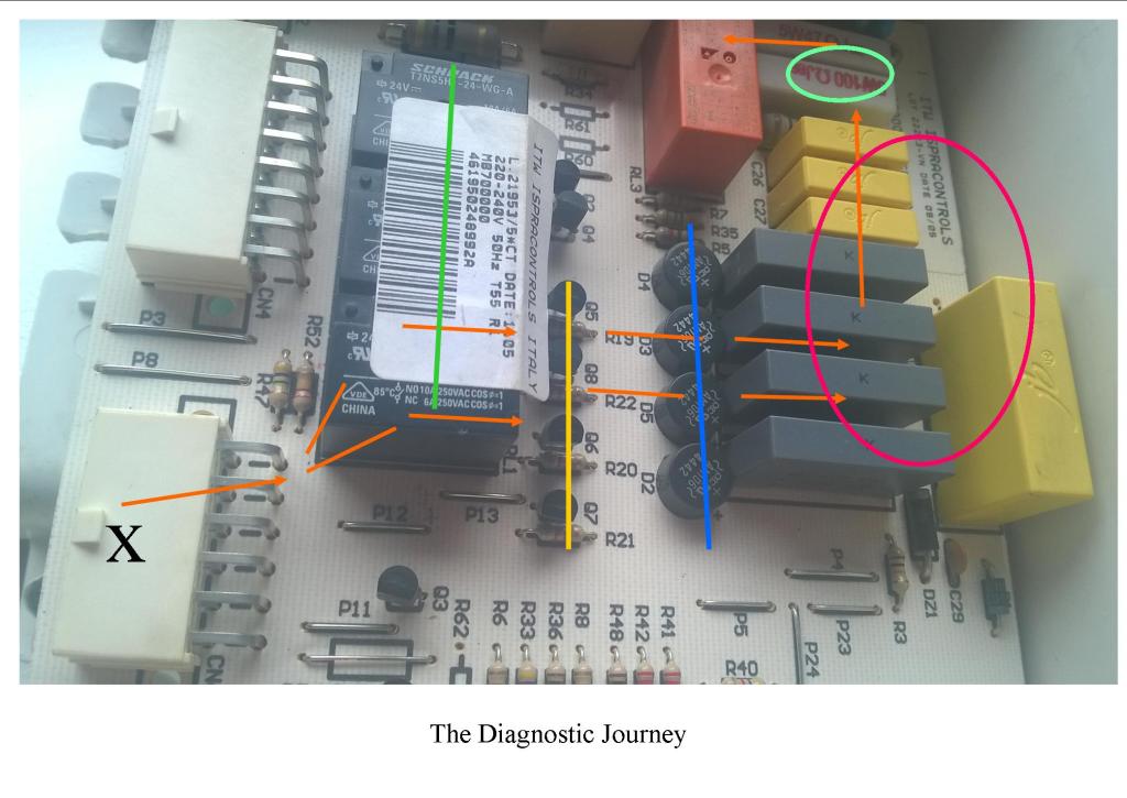
The board is now turned 90 degrees. The capacitors have been changed on this one but that matters not, colours change but it is what is marked on the parts that matters, so it’s still the same board. Remember I’m working against the normal direction of signal – backtracking*. Using my meter (just using continuity) I checked and followed the pathway, as the orange arrows show. The first major components encountered are a set of 3 relays** (green line) each serving separate circuits – one being the heater (plus fan and ice maker IIRC) – all 24 volt DC. Check for damage; burning, melting, smelling etc. I suspected the problem was capacitor or resistor related (common suspects) so I resisted the temptation to desolder the relay to check it. Remember to check the underside of the board for visible anomalies/damage.
*What I mean by this is the operation of the heater element goes from the board to the element. Remember we are going backwards down the current pathway.
**For those in doubt, larger components drawing heavier current are switched by a lighter current through relays. That’s what these are doing.
The line (yellow) of components coming up next are transistors – used to regulate power. They looked pristine so I moved on. The blue line indicates Inverters, devices that change AC to DC. This means that our journey so far has been back along DC circuits. On crossing the blue line we’re now in AC territory – mains power. So coming from the correct direction this mean mains power is converted to lower DC power here. This is pretty standard and most of your household electronics have an internal device to convert the mains power to a lighter load for delicate small components. TV’s DVD’s PC’s and so on…… Lots of stuff in Upper case.
Ahead of us now – looking like a miniature 60’s tower block estate – is a clutch of capacitors. A whole set is widely available online indicating it’s a common repair item. The set usually runs at 12-15 quid ($18). There’s also a set for the front PCB (behind the door display) so don’t get the wrong ones. Bearing all that in mind it is worth replacing the set – if they’re old and haven’t gone yet – it may be just a matter of time……….
They are ringed in pink. Whipping them all out (and back in) to test or replace takes about 20 mins, maybe twice that if it’s your first time. But quick nonetheless. Crikey, Double Entendres everywhere! Come on, keep it clean people!
The items circled in turkws… turqios… turqusoi… turqiosus…. greeny blue are ceramic resistors. Tucked down in the gap in front is a large carbon resistor. You can check this visually and by multimeter. The ceramic resistors (white) are there to control the inrush of current and can withstand high energy/temperatures, thereby protecting the capacitors we’ve just passed. They were tested and passed.
Finally we come to the little red brick box. I’ve seen this described as a capacitor elsewhere online. It is not! It’s a relay. One of the great things about the Internet, apart from dogs on bicycles and tiny cats in teacups, is the amount of data available for stuff like electronics. I actually know very little – Ohhh.. you can tell? – so I read the info off the top of these components and look it up. No brainer. Most of what I’ve learnt is from identifying parts as I come across them during a fix. Some electronic schematics (often found at the end of a manual) help to identify parts – the symbols and serial numbers can be viewed online. Easy Peasy Sherlock. This is important when sourcing new parts.
While still on the board I gave the relay a flick with my fingernail. Either the rattling noise indicated the presence of a tiny irritated flamenco dancer, or it was knackered. I desoldered it, checked with my basic Spanish (Hola!), ruled the Flamenco option out, and confirmed the failure by multimeter. The role of this component is to switch between the compressor running and the defrost mode. A running compressor is feeding the evaporator making everything very cold. To then run the defrost at the same time defeats the object of defrosting. Therefore the compressor turns off and the relay flicks over and switches on the defrost circuit.* The magnetic switch inside was broken and although the circuit and everything all the way back was actually functioning it just wasn’t getting turned on switched on. Therefore I checked for continuity on one side of the switch, then the other – there was nothing!
*When defrost is complete it flicks back across and the compressor runs. I am informed this may be switched by timer chip and/or thermally, dependant on make.
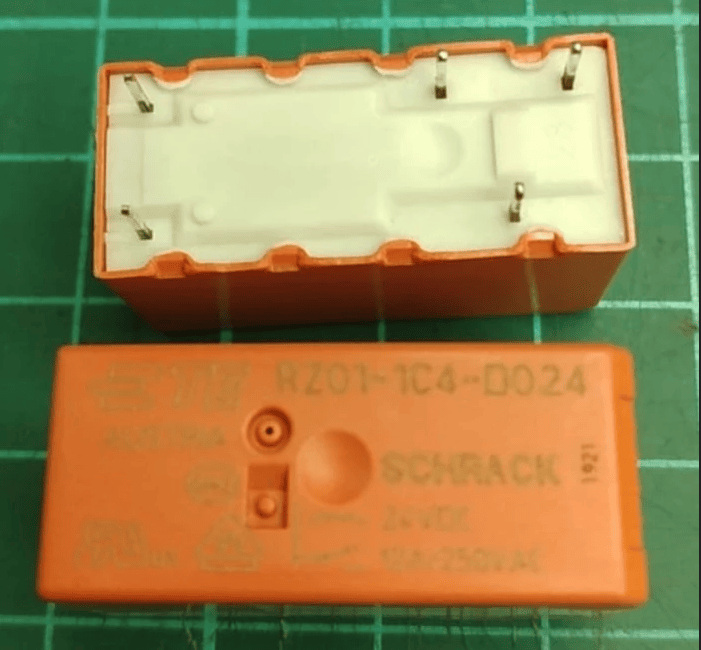
So here’s the little chap in question. RZ01-1C4-DO24 SHRACK will be all you need. Bang the number into your chosen site, pick your favourite and order. The pins on the underside means it only fits one way – my images plus your own will confirm if needed. As previously stated this saved a lot of money*. I did not have to wait for a repairman to rock up, nor go without my appliance while he/she ordered in the spare . A spare board that is, as I doubt any other options were on the table. Tradesmen want a fast in and out with maximum return – I used to be an electrician remember? As a side thought I suspect they would have kindly ‘disposed’ of the customers board – repairing it to sell to another customer at a bargain price! What a benevolent world we live in.
*£45 on whirlpool spares site, £6 on eBay. Exact same part. You’re paying £39 for the site to confirm what you can read off the part yourself. Do you not trust your own eyesight?
So there we have it. A long rambling story with hopefully some useful bits along the way.
This has been difficult, as deciding what to leave in or out, while still providing as much info as possible: but not over complicating the subject, nor leaving blindspots and unanswered questions, has been a nightmare. If I’ve mind fucked some people I can only apologise. For the clever ones I may have omitted some bits or not been clear on others. Again I’m trying to provide a way forward – not impress anyone with loads of tech stuff. Reading through a couple of times may help (it did for me). Additionally, if you actually have eyes on the appliance it helps a lot. My intention was to enlighten not be condescending. All I hope is something valuable can be extracted.
There’s lots of components on this board and my journey is only one, yours may be very different. Perhaps the path may be a little less dark now. The point being if you don’t search for a solution you won’t find one, and even if you don’t at least you tried and perhaps the experience will provide a win next time around.. That alone can be very empowering.
Images and Article Copyright © 2026 by L.C McCarthy

